What is a PROFIBUS Protocol?
PROFIBUS defines the technical features of a serial field bus system, by which distributed digital automation devices, from field to cell level, can be networked together.
It is a multi-master system and so allows the combined operation on one bus of several automation, engineering, and visualization systems with remote peripherals.
Protocol Architecture
This protocol depends on Master-Slave architecture:
Master
Master determines data traffic on the bus and can send messages without an external request if it is in possession of the bus access token.
Masters are also described as active stations.
Slave
The slave is a peripheral device, such as input and output devices, valves, drives, and transmitters. They do not receive a token authorizing bus access.
This means that they can only acknowledge messages received or, at the request of a master, send messages to it. Slaves are described as passive stations.
They only require a small portion of the bus protocol, which means they make implementation possible with little effort.
Profibus Protocol Limitations and Characteristics
| Organization | PROFIBUS & PROFINET International |
| Physical Layer | RS-485 |
| Transmission speed | Up to 12Mbit/sec |
| Address Space | Up to 126 |
| Telegram | 244 Bytes |
| Technology Architecture | Master/Slave |
| Max Cable Length Between two devices | 100 Up to 1200 Meter That depends on the bit rate used |
| Connectivity | PA + Others |
Steps to configure a PROFIBUS network
Our network consists of:
- Siemens PLC S7-400 (DP Master) CPU 412-2DP
- Siemens PLC S7-300 (DP Slave) CPU 312C-2DP
- PROFIBUS cable (RS485 cable)
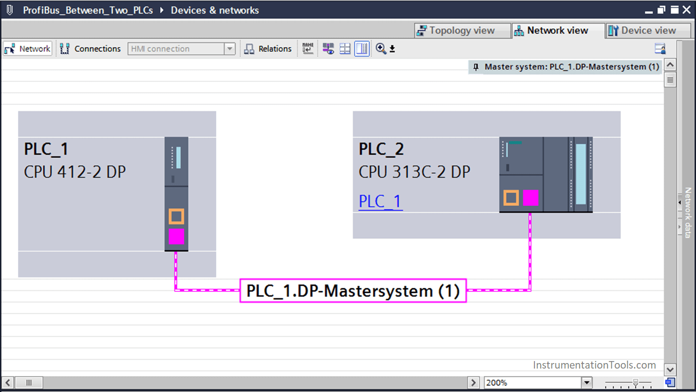
Step 1:
First of all, we will make our Hardware configuration and connect the two PLCs through (DP port)
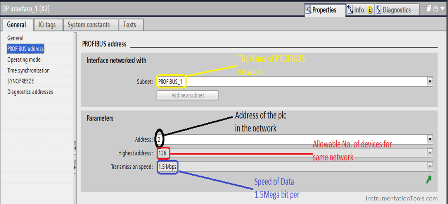
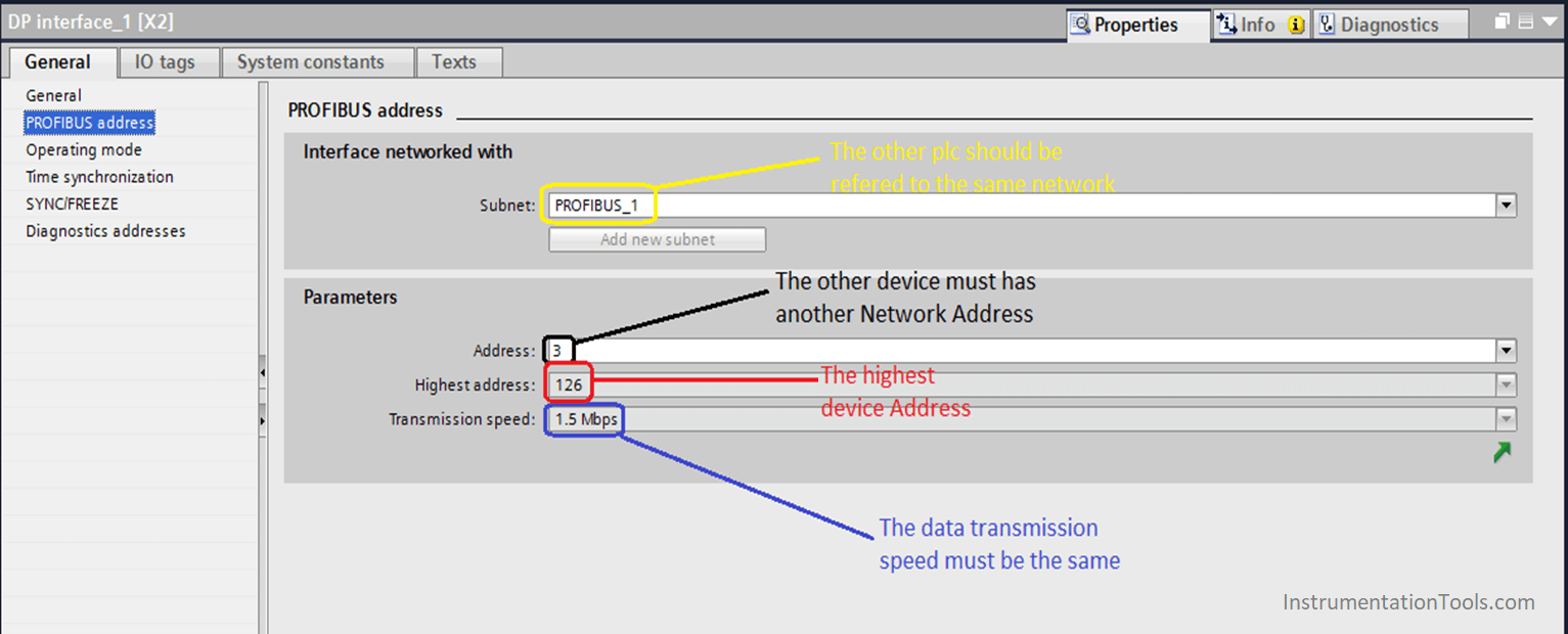
Step 2:
Then we are going to set the DP address and parameters of the PLC by clicking on the PROFIBUS port for (S7-412)
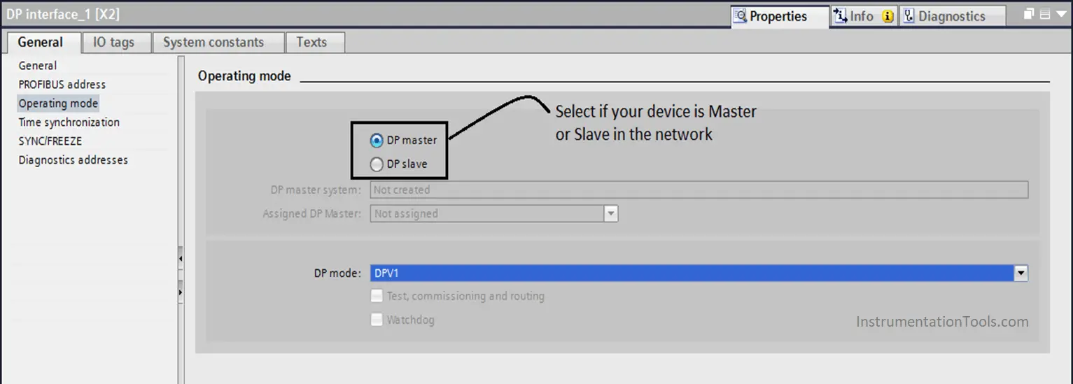
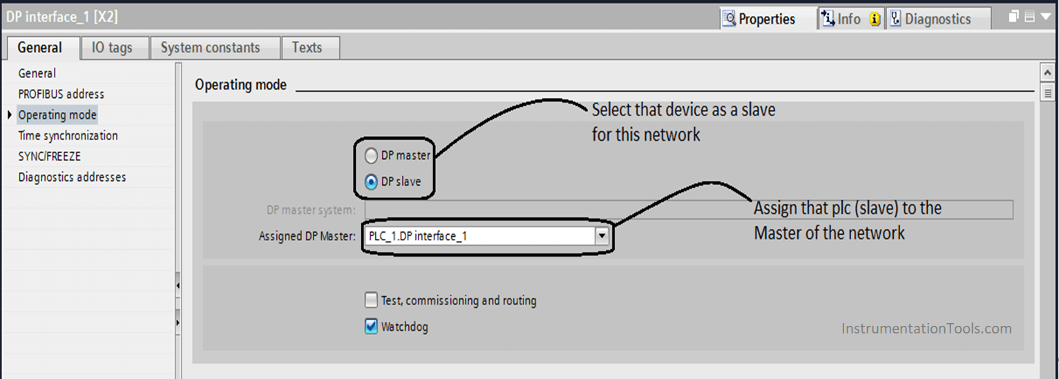
Step 3:
Then we have to set the parameters for the other PLC (S7-312)
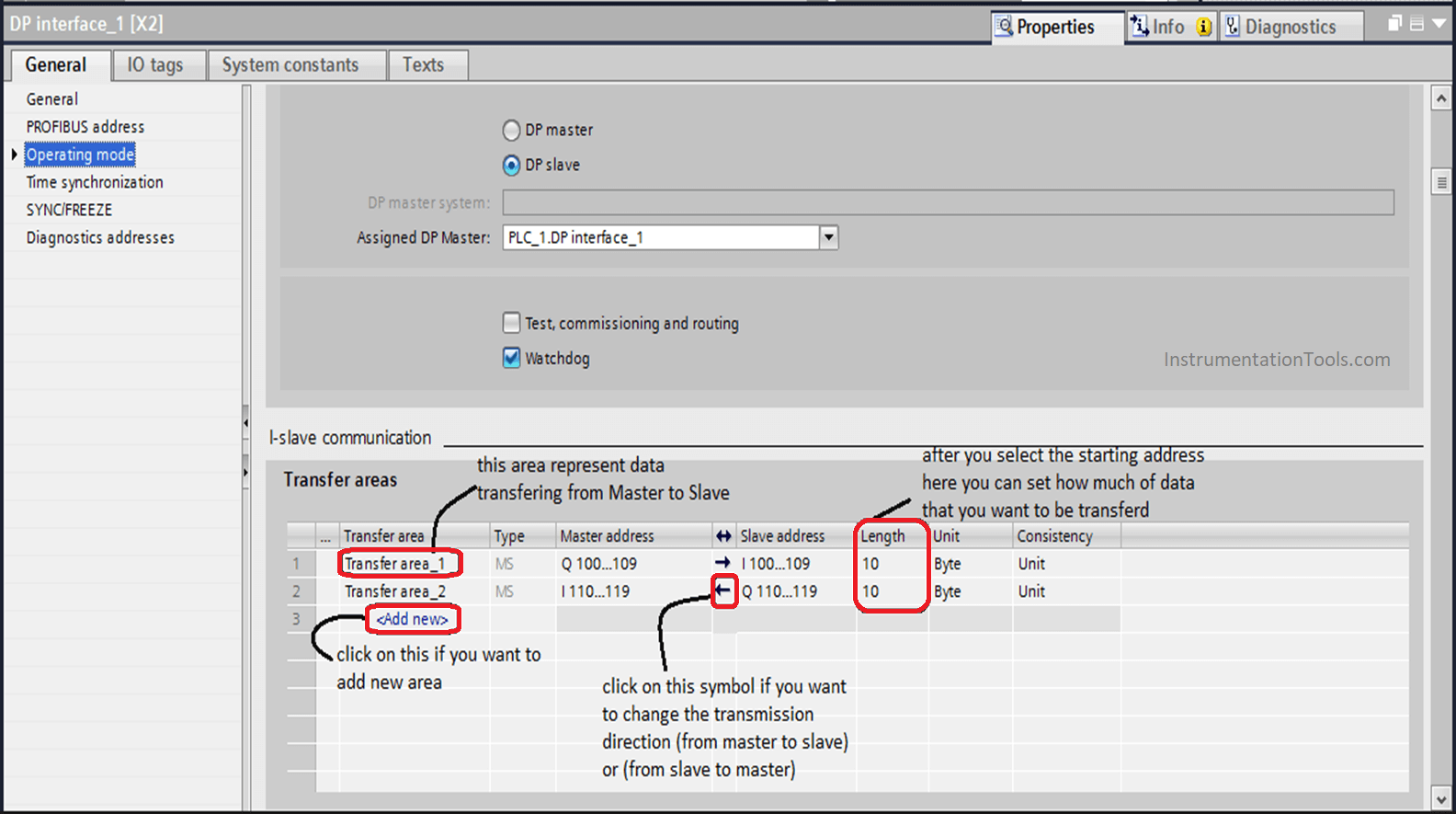
Step 4:
You should be aware that the communication between the two PLCs via PROFIBUS protocol stands on the Input / Output Memory of the devices, for this part you can customize your data addressing for the communication.
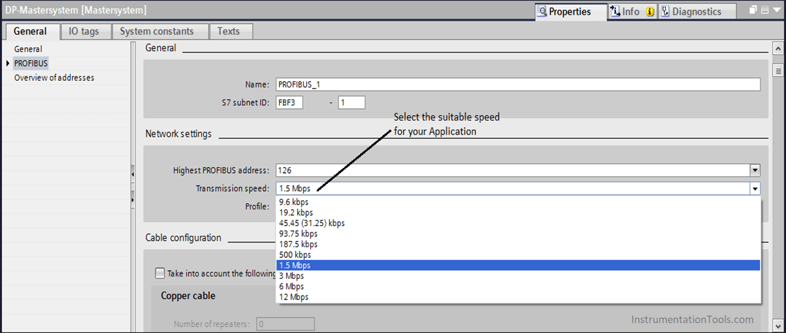
Step 5:
If you want to change transferring speed you have to click on the PROFIBUS connection between the two PLCs then you can change from here,
Finally, you can download your program on the PLCs.
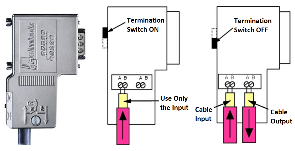
Little Tip in the hardware connection, for the PROFIBUS connector there is a small switch that called Termination resistor.
You have to ensure that it is ON for the two PLCs (as the network consists just of two devices), but in case of that you have a big network that consists of several PROFIBUS devices, you have to make this switch ON for just the first and last devices as they have just Ingoing cable for the connector, and all other devices that they are in between its Termination Resistor should be OFF as there are Ingoing and Outgoing cables for the same connector.